
MBS Universal Gateway XT Series
Core + M-Bus
Consumption data belongs in the system.
Meters provide measurement data. To gain a complete picture of building operations, this information must be integrated with energy and automation systems.
The MBS Universal Gateway Core + M-Bus from the XT Series connects M-Bus meters directly to the MBS Gateway platform. The central data point manager collects the measured values and makes them available to the desired target protocols. This allows consumption data to be used wherever it needs to be analyzed or processed further.
Available now
Using M-Bus Meters for Energy Management and Building Automation
The direct M-Bus connection is intended for projects with compatible meters and M-Bus infrastructure. Which measurement values are retrieved depends on the connected devices and the project configuration.
Depending on the configuration and licensing, other communication protocols such as BACnet/IP, Modbus TCP, MQTT, or OPC UA can be combined with the M-Bus data. The Data Point Manager assigns the meter readings to the configured data points and target systems. This allows measurement and consumption data to be made available for analysis, control systems, or energy management.
Which model is right for your project?
The Universal Gateway Core + M-Bus is the right model to use when an M-Bus system needs to be physically connected directly to the gateway.
If only IP-based communication protocols such as BACnet/IP, Modbus TCP, MQTT, or OPC UA are used and no additional M-Bus connection is required, the Universal Gateway Core provides the ideal foundation.
If another bus system is to be connected directly in addition to M-Bus, a corresponding combined Core + version is required, depending on the available device model.
Technical Basis of the XT Series
The Universal Gateway Core + M-Bus is based on the new XT Series hardware platform. A more powerful CPU and expanded main memory provide additional capacity for demanding integration tasks. A completely redesigned web interface is also available to simplify configuration and commissioning.
The new hardware also enhances the gateway's security architecture. At its core is an integrated secure element. It provides the technical foundation for a secure boot process that can detect tampering with the bootloader or kernel.
Digital certificates can be securely stored in the Secure Element. It also provides the foundation for encrypting the entire file system on the SD card. This allows both the system and customer-specific user and configuration data to be stored in encrypted form.
Configuration and Commissioning
The web interface allows you to configure and analyze the gateway. This includes, among other things, setting network parameters, creating and managing data points, and mapping information between M-Bus and other communication protocols.
The appropriate GSD file is provided for integrating the gateway into the M-Bus configuration.
A REST API also makes it possible to automatically configure settings from external applications. This is particularly relevant for OEM applications and recurring device configurations.
Important Note:
Please ensure that your gateway has been configured for the specific application before commissioning.
Three Steps to Your Gateway
Define Systems and Interfaces
Specify which M-Bus system is to be connected and with which building automation, energy, or IT systems data is to be exchanged.Determine Data Point Capacity
Determine how much information needs to be transferred between the systems involved. Then select the appropriate data point package.Configuring Protocols
Determine which additional communication protocols are required and how the data should be mapped between M-Bus and the respective target systems.
Your gateway thus consists of the Core + M-Bus device model, the required data point capacity, and the planned communication protocols.
Made in Germany
The XT Series circuit boards are manufactured in Europe. Final assembly takes place at the MBS facility in Krefeld.
MBS develops its own gateway platform and supports projects from selection and planning through commissioning to long-term support.
Downloads and Technical Documentation
Item Number: 11-0093
Data Sheet: Technical Specifications, Dimensions, Interfaces, and Environmental Conditions. ›
DE | EN
Quick Start Guide
Instructions for installation, connection, and initial setup. ›
ManualDetailed information on project planning, configuration, and operation will be available shortly. ›
Firmware Updates
Latest firmware and installation instructions. ›
RFP Text
Product description for planning and bidding. ›
FAQ and Help CenterAnswers to questions about configuration, operation, and technical issues will be available shortly. ›




Technical data
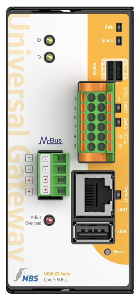
LEDs
Power: Lights up as soon as the device is connected to a suitable
power supply
ST.: Multicolor status LED
DIP switches
Terminating resistor: 120 Ω
Bias: Standby voltage for RS485 interface
PWR - Power
VCC IN: 12 to 24 V DC power supply
GND IN: Ground connection to the power supply
COM1 | RS485
[+]: non-inverted line
[-]: inverted line
SGND: signal ground connection
COM2 | RS232
TX: Transmit line
RX: Receive line
SGND: Signal ground
Interface LEDs
Flash blue when the device is sending data
Flash green when the device is receiving data
LAN
RJ45: 10/100 Mbit/s Ethernet
LED:
Lights up when a link is present
Flashes during data traffic
USB
Not used
, 5 V, max. 500 mA
M-Bus
LED
MBus RX
MBus TX
MBus Overload
M-Bus
+ M-Bus connection
+ M-Bus connection
- M-Bus connection
- M-Bus connection
Integrated M-Bus level converter
for up to 30 standard loads max. 1.5mA, master operating mode
Specifications:
Power consumption: 3 .1 to 5.7 watts (1 to 30 M-Bus loads connected)
Weight: 405 g
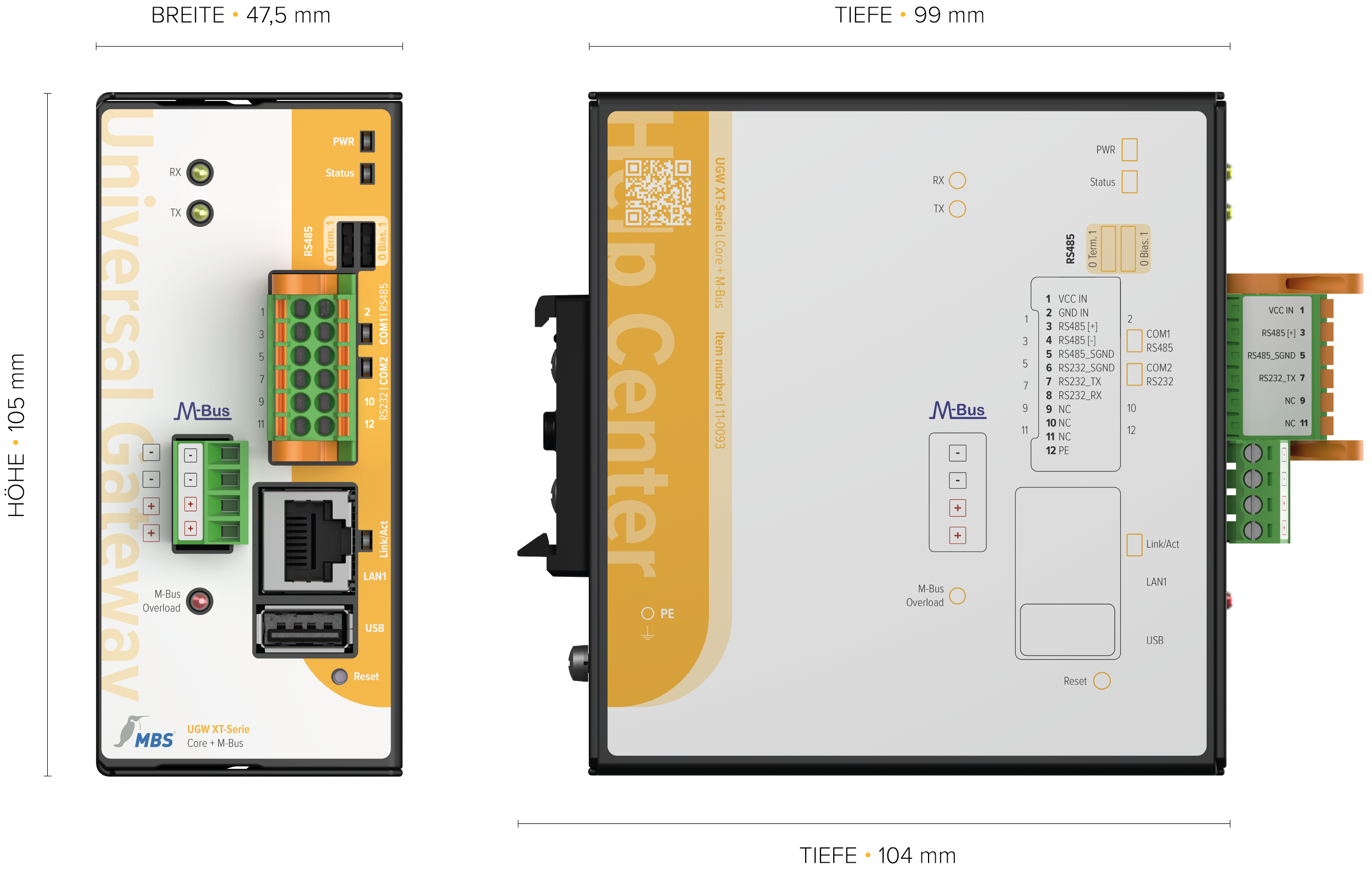
Dimensions: Height : 105 mm, Width: 47.5 mm, Depth: 99 mm
(Depth: 104 mm including DIN rail mount)
Ambient temperature: 0 to 45 °C
Rel ativehumidity: 20 to 80%, non-condensing
Protection class: IP20
Mounting: TS35DIN top-hat rail according to EN 60715
Frequently Asked Questions About the XT Series Universal Gateway Core + M-Bus
-
Yes, provided that BACnet/IP has been configured for the project and the required M-Bus values have been mapped to the BACnet data points.
-
If M-Bus meters are to be connected directly via a physical connection. The Core does not have an additional built-in M-Bus interface.
Would you like to use the Universal Gateway Core + M-Bus in your project?
Are you already familiar with the systems involved, the communication protocols, and the approximate number of data points?Configure the appropriate Universal Gateway ›
Are you still unsure about the configuration, or do you need a specific quote?
Request a consultation or quote ›
Phone: +49 2151 7294-0
Email: vertrieb@mbs-solutions.de